
In large-scale industrial processing plants, commercial complexes, and power substations, distribution power cables rarely travel in simple wall conduits. Thousands of thick, multi-core armored copper and aluminum cables route across ceiling spaces and pipe racks using overhead Cable Tray & Support Systems.
Designing these containment networks requires structural civil engineering calculations. A Perforated GI Cable Tray or Ladder Tray isn’t just a guide channel; it is a load-bearing beam suspended overhead.
If an engineering team underestimates cumulative cable weights or places support brackets too far apart, the metal structure will buckle under the load. This leads to structural deflection, pinched cable insulation, phase-to-earth faults, and potential overhead collapses.
Mechanical Deflection Limits: Understanding NEMA and IEC Standards
When a cable tray rests on two structural support brackets, it bends slightly downward in the center under its own weight and the weight of the cables. This downward bend is called Deflection.To maintain structural integrity and visual alignment, international standards (such as NEMA VE 1 and IEC 61537) enforce strict deflection limits:
- The L/200 Deflection Rule: Maximum allowable mid-span deflection must not exceed 1/200th of the support span length (L).
- For Example: On a 3000mm (3 meter) support span, the maximum allowable mid-span sag under full load is:
DeflectionMax = 3000 mm/ 200 = 15 mm
Exceeding this 15mm limit stresses the mechanical splice joints connecting adjacent tray sections, stripping coupling bolts and creating sharp edges that cut into cable insulation during thermal expansion cycles.
Calculating Total Load Capacity: Dead Loads vs. Concentrated Live Loads
To size the required sheet thickness (e.g., 1.6 mm, 2.0 mm, 2.5 mm) and bracket spacing, engineers must calculate the total design load (WTotal) per linear meter:
WTotal = ( WCables + WTray ) X Safety Factor + WConcentrated
- Cable Load (WCables) : Cumulative weight ( kg/m ) of all armored power, control, and instrumentation cables packed inside the tray bed.
- Safety Factor Buffer: A non-negotiable multiplier (typically 1.5x) to accommodate future cable additions during facility expansions.
- Concentrated Live Load (WConcentrated) : Represents static physical forces, such as an installer stepping or pulling against the tray during maintenance. Standards mandate accounting for a concentrated load of at least 90kg (200 lbs) at mid-span.
Support Bracket Architecture and Anchoring Physics
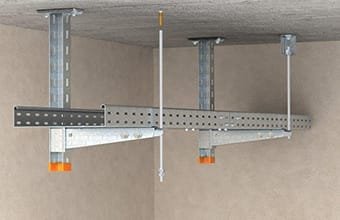
Even the strongest Perforated GI Cable Tray will collapse if its mounting supports fail. The containment line relies on three primary mounting configurations:
[ Trapeze Ceiling Hanger ]                [ Cantilever Wall Bracket ]
      ||        ||                                    ||
      ||        ||                          ||===================
      ||        ||                          || [ Cable Tray Bed ]
======||========||======                    ||===================
|   [ Cable Tray Bed ] |                    ||
========================                    ||<-- Structural GI L Clamp
| Support Configuration | Structural Loading Dynamics | Best-Suited Installation Zone |
| Trapeze Hangers | Dual threaded drop rods holding a bottom strut channel. Distributes load symmetrically across ceiling slabs. | High-density central cable runs along main plant corridors and ceiling decks. |
| Cantilever Brackets | Single horizontal arm bolted to a vertical wall or column. Subject to severe bending leverage at the anchor point. | Secondary feeder runs along perimeter walls, civil columns, and building beams. |
| Pipe Rack Structural Clamps | Heavy-gauge GI L Clamps or U-bolt assemblies anchoring trays directly to structural H-beams or Electric Poles. | Outdoor yard pipe bridges, process plant gantries, and open-air infrastructure. |
Installation Best Practice: Never place a sheet metal splice joint (where two tray sections bolt together) directly on top of a support bracket or at the absolute center of a span. Splice joints should be positioned at roughly 1/4th of the distance from a support point—the point of zero bending moment—to maintain structural rigidity across the entire run.
Partner with an ISO-Certified Cable Management Manufacturer & Exporter
Engineering safe overhead containment networks demands certified metal sheet gauges, precision slot punching, and rigorous mechanical load testing. Sourcing lightweight commercial trays or unvetted support brackets leaves your plant infrastructure vulnerable to tray sagging, joint shearing, and costly cable damage.
As a leading manufacturer, supplier, and exporter, Satya Electrical manufactures heavy-duty Perforated GI Cable Trays, Ladder Trays, Support Systems, Strut Channels, GI L Clamps, and Structural Accessories. Every component is engineered to comply strictly with international load standards and built to handle aggressive industrial environments.

 Users Today : 2
 Users This Month : 102
 Total Users : 1315