
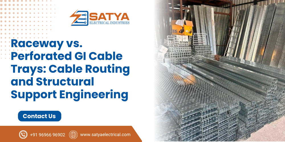
In industrial plants, commercial complexes, and power utility networks, laying thousands of meters of power, control, and instrumentation cables requires a rigid, organized support system. Improperly supported cable runs lead to insulation sagging, thermal heat buildup, electromagnetic interference (EMI), and difficult maintenance access.
Engineers face two primary choices for enclosed overhead or under-floor cable routing: Raceway (Solid-Bottom) Cable Trays and Perforated GI Cable Trays.
Understanding when to specify raceways versus perforated trays—and how to engineer their structural support matrix using G.I. Slotted C-Channels, Z-Channels, and L Clamps—is essential for building compliant cable management systems.
Perforated GI Cable Trays vs. Raceway Cable Trays
PERFORATED CABLE TRAY (Ventilated)    RACEWAY CABLE TRAY (Solid Enclosed)
   +-----------------------+          +-----------------------+
   |  o   o   o   o   o    |          |                       |
   |  o   o   o   o   o    |          |    Solid Sheet Bottom |
   |  o   o   o   o   o    |          |    (Full EMI Shield)  |
   +-----------------------+          +-----------------------+
   [ High Heat Dissipation ]          [ Dust & EMI Protection ]
| Technical Feature | Perforated GI Cable Tray | Raceway Cable Tray (Solid Bottom) |
| Ventilation & Cooling | High air circulation through uniform slot perforations. Ideal for power cables emitting I2R heat. | Enclosed design restricts air flow. Power cables require higher thermal de-rating. |
| Environmental Protection | Open to falling debris, dust accumulation, and water drips. | Provides continuous physical protection against dirt, falling tools, moisture, and chemical splashes. |
| EMI / RFI Shielding | Moderate electromagnetic shielding. | High continuous metallic shielding; protects sensitive signal/instrumentation cables from external noise. |
| Drainage | Water and liquids drain automatically through bottom slots. | Requires sloped mounting or drain holes if installed in wash-down areas. |
| Primary Application | Heavy LT/HT Power Cables, Motor Feeders, Plant Overhead Trays. | Control Wiring, Data/Telecom, Instrumentation, Under-floor cleanrooms. |
Mechanical Load Math & Deflection Standards
According to NEMA VE 1 / IEC 61537 standards, a cable tray assembly must support the combined weight of installed cables, future expansion allowances (25%), and temporary concentrated live loads (such as maintenance installers) without exceeding strict deflection limits.
       Load (W = Cable Weight + Concentrated Load)
   =================================================  <--- Cable Tray
         ^                                   ^
         |--------- Support Span (L) --------|
The maximum allowable mid-span deflection (δ) between two structural support brackets is typically restricted to:
δMax = L/200
Where:
- L = Support span distance in millimeters (typically 1.5m to 3.0m).
If a support span (L) is 2000 mm, the maximum downward bending mid-span must not exceed 10 mm under full cable load. Exceeding this limit distorts tray joint connectors and places tensile stress on the cables inside.
Structural Support Architecture: Channels and Clamping Hardware
A cable tray system is only as strong as the structural steel matrix anchoring it to building beams, roof trusses, or concrete walls.
[ Concrete Ceiling / I-Beam ]
             |
             |---> Threaded Rod / Channel Hanger
             |
  [ G.I. Slotted C-Channel / Z-Channel ]  <--- Structural Trapeze Support | +---> Secured with Heavy-Duty G.I. L Clamps & Hold-Down Clips
             |
  [ Perforated / Raceway Cable Tray ]
- G.I. Slotted C-Channels (Strut Channels): Act as the primary cross-beam (trapeze hanger) underneath cable trays. The uniform continuous slots eliminate the need for field drilling, allowing quick height adjustments and multi-tier tray stacking using threaded rods.
- G.I. Z-Channels: Provide rigid side-wall mounting and offset wall brackets where overhead ceiling suspension is unavailable. The offset Z-profile offers high torsional resistance against side-loading forces.
- Galvanized Iron (G.I.) L Clamps: Heavy-gauge 90° connection brackets used to join strut channels to vertical drop rods, wall plates, or steel building columns. Hot-dip galvanization ensures the clamps match the corrosion resistance of the trays.
- Hold-Down Clamps & Expansion Splice Plates: Hold-down clamps anchor the tray secure to the support channel while allowing microscopic longitudinal sliding to accommodate thermal expansion and contraction across long indoor/outdoor runs.
Installation Rule: Never run high-voltage LT/HT power cables and unshielded 24V DC instrumentation/signal cables inside the same un-divided cable tray. If routing space forces them into a shared raceway, you must install a continuous metallic G.I. Divider Barrier (Separator Strip) grounded to the main earth grid to prevent electromagnetic cross-talk.Source Complete Cable Management & Structural
Source Complete Cable Management & Structural Support Infrastructure
Engineering long-term cable support infrastructure demands exact load-deflection math, high-grade galvanization, and precision-manufactured support profiles. Using light-gauge un-galvanized channels or under-sized trays leads to tray sag, insulation abrasion, and costly structural failures.
As an ISO-certified manufacturer, supplier, and exporter, Satya Electrical produces a complete range of Perforated GI Cable Trays, Raceway Cable Trays, Ladder Trays, Slotted C-Channels, Z-Channels, G.I. L Clamps, and Support Accessories. Every component is fabricated from high-grade steel with uniform galvanization to withstand aggressive industrial environments.

 Users Today : 2
 Users This Month : 102
 Total Users : 1315