
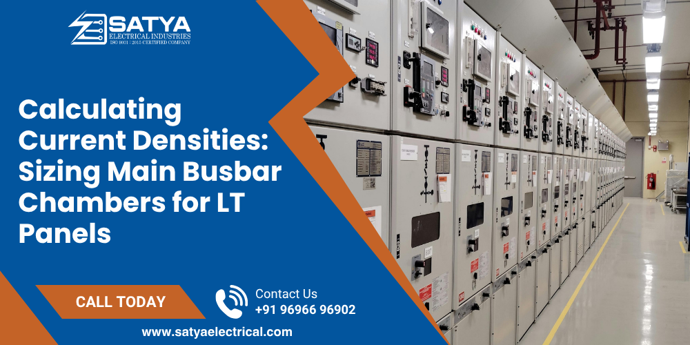
In the heart of any heavy industrial facility, the main Low Tension (LT) switchgear assembly bears the massive electrical burden of distributing thousands of amperes flowing from the main power transformer. Within these enclosures, traditional cables become unmanageable due to space limits and bending radii. Instead, power routes through rigid, high-purity metal bars housed inside a dedicated Bus Bar Chamber.
Sizing these chambers requires precise engineering calculations. Using loose estimates or cutting corners on the metal’s cross-sectional area risks catastrophic failure.
Overlooked variables like electromagnetic skin effects, restricted airflow, and high short-circuit fault currents can turn a busbar chamber into an electrical oven, quietly destroying circuit breaker components and causing catastrophic phase-to-phase short circuits.
Copper vs. Aluminum: The Real Current Density Math
A common error among procurement teams is expecting a 1:1 replacement size when swapping copper bars for aluminum to save budget. The underlying metallurgy demands completely different design footprints.
- Electrode Grade Copper: Provides exceptional electrical conductivity. In enclosed, unventilated LT panels, engineers calculate a safe current density baseline of roughly 1.2 to 1.5 A/mm2 of cross-sectional area.
- EC Grade Aluminum: Possesses roughly 61% of the conductivity of copper. To carry the exact same amperage load safely, an aluminum bar requires a significantly larger cross-section, operating at a lower current density baseline of approximately 0.8 to 1.0 A/mm2.
If an engineering team simply copies copper dimensions using aluminum, the higher internal electrical resistance will cause uncontrollable thermal runaway.
The Skin Effect: Why Bar Geometry Matters Above 1000A
When handling Alternating Current (AC), electrical current does not flow evenly through the entire thickness of a solid metal bar. Instead, the alternating magnetic fields push the current toward the outer edges—a phenomenon known as the Skin Effect.
[ Solid Square Busbar Profile ]       [ Specialized Laminated / Multi-Leaf Profile ]
  ===========================            ==================   ==================
  | XXXXXXXXXXXXXXXXXXXXXXX |            | XXXXXXXXXXXXXX |   | XXXXXXXXXXXXXX |
  | XXX (Idle Core Zone) XXX |            ==================   ==================
  | XXXXXXXXXXXXXXXXXXXXXXX |            | XXXXXXXXXXXXXX |   | XXXXXXXXXXXXXX |
  ===========================             ==================   ==================
 (Current crowds the outer skin,       (Splitting into thinner parallel leaves
leaving the center underutilized)     multiplies the useful conductive surface)
In heavy applications where current exceeds 1000A, the core of a very thick, solid square busbar goes almost entirely unused.To overcome this without buying unnecessary, expensive raw metal, panel builders use multiple thinner bars running in parallel per phase (known as a multi-leaf configuration, such as two or three 50 x 10 mm bars rather than a single solid block). This structural geometry maximizes the usable surface area, facilitating rapid heat dissipation and reducing total energy losses.
Critical Engineering Metrics for Main Busbar Chambers
To pass strict quality audits (such as CPRI short-circuit tests), a busbar chamber must be built to survive intense physical and environmental pressures:
| Engineering Parameter | Copper Busbar Framework | Aluminum Busbar Framework | Structural Safety Purpose |
| Max Operating Temp | 85°C to 90°C Maximum | 85°C Maximum | Prevents the joints from oxidizing rapidly and breaking down. |
| Phase-to-Phase Clearance | Minimum 32mm in air | Minimum 32mm in air | Eliminates the risk of electrical arcing across phases during voltage surges. |
| SMC/BMS Support Interval | Every 400mm to 600mm | Every 350mm to 500mm | Holds bars rigid against massive magnetic repulsion during a short circuit. |
| Joint Contact Treatment | Electro-tin plating or Silvering | Anti-oxidant grease + bimetallic strips | Stops galvanic corrosion when mating dissimilar metals. |
Torque Vetting Rule: Over-tightening or under-tightening the bolts holding busbar joints together causes localized hot spots. Under-tightened joints have high electrical resistance, while over-tightened steel bolts stretch beyond their elastic limit, causing the metal joint to warp over time. Always specify precise torque wrenches to tighten all structural joints to exact Newton-meter (Nm) factory specs based on bolt sizes.
Deploy Safely Vetted, CPRI-Compliant Power Distribution Assemblies
Engineering long-lasting LT switchgear requires deep metallurgical knowledge and precision fabrication machinery. Lowering material grades or skimping on the spacing of insulated supports leaves your main plant infrastructure exposed to severe short-circuit collapses and costly facility blackouts.
At Satya Electrical, we design and manufacture high-conductivity Busbar Chambers, LT Distribution Panels, and Heavy-Duty Switchgear Enclosures built using high-purity copper and aluminum alloys, precisely configured to handle your facility’s exact fault ratings.

 Users Today : 3
 Users This Month : 113
 Total Users : 1326