
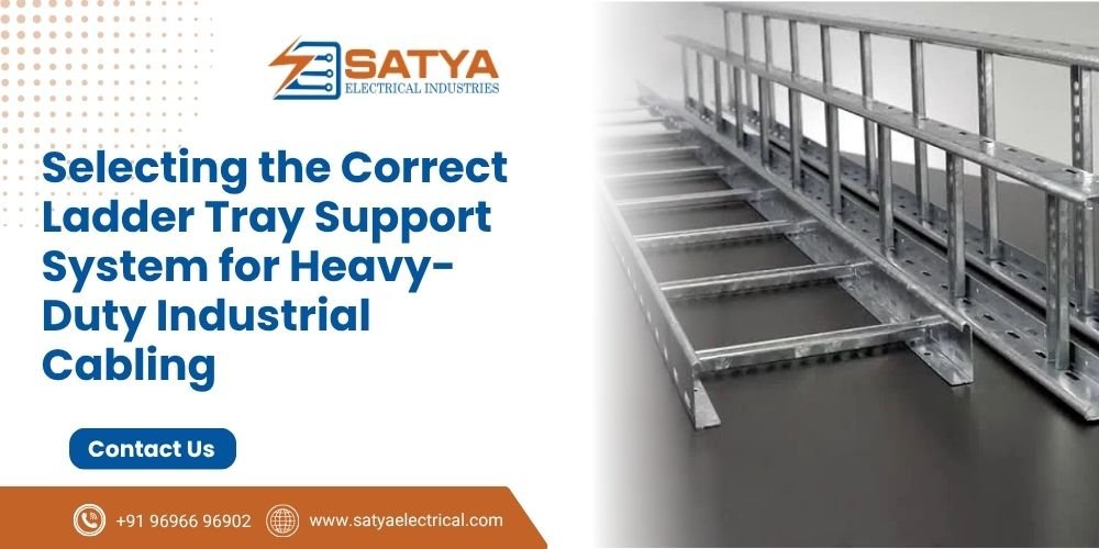
When routing high-amperage, thick-jacketed armored power cables across an industrial facility, traditional enclosed conduits or Raceway Cable Trays become highly impractical. The massive physical diameters, heavy weight loads, and high operational heat dissipation of these lines demand open-air structural frameworks. This is why a heavy-duty Ladder Tray layout is the preferred industry choice.
However, designing an overhead cable highway isn’t just about selecting a metal profile that fits across your layout. If your engineering team fails to calculate total cable weight distributions or overextends the distance between structural hangers, the entire system will buckle under stress.
Preventing structural deflection requires a rigorous understanding of support span geometry and strict compliance with global installation frameworks.
Mechanical Physics of Cable Support: Understanding Structural Deflection
When power cables fill a tray, the assembly behaves like a continuous structural beam resting over multiple elevated points. The downward weight of the cables creates structural stresses that attempt to bend the frame out of alignment.
- Structural Deflection: This is the physical distance the middle of a cable tray section sags downward between two supporting brackets. Under standard engineering parameters set by NEMA VE 1, maximum allowable vertical deflection should never exceed 1/200th of the total span length to protect structural integrity over decades.
- The Rung Spacing Factor: Heavy-duty power cables apply extreme concentrated loads. If your rung spacing is too wide (e.g., exceeding 300mm), the heavy cables can warp the individual rungs downward, straining the cable jackets and running the risk of sharp metal edges slicing into live lines.
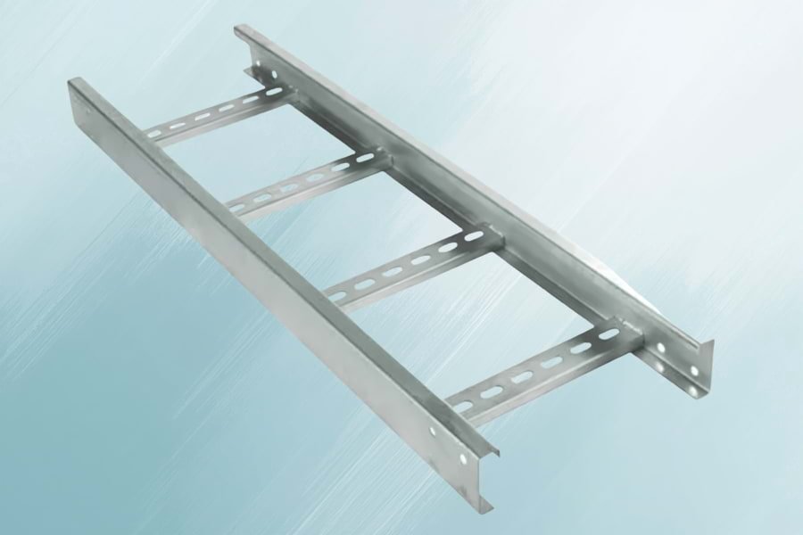
Critical Engineering Metrics for Ladder Tray Load Sizing
To maintain an unyielding cable containment line, your installation blueprints must balance weight limits with support spacing intervals:
| NEMA Load/Span Class | Working Load Capacity | Maximum Allowed Support Span | Typical Industrial Application |
|---|---|---|---|
| Class 8A | 74 kg/m | 2.4 Meters (8 Feet) | Light-to-medium industrial sub-stations |
| Class 12C | 149 kg/m | 3.6 Meters (12 Feet) | Heavy processing facilities & chemical plants |
| Class 20B | 298 kg/m | 6.1 Meters (20 Feet) | Long-span outdoor pipe racks & utility bridges |
Engineering Protocols for High-Capacity Support System Frameworks
[ Overhead Concrete I-Beam / Ceiling Structure ]
||
[ Hanging Threaded Rods ]
||
======================||====================== <-- [ Ladder Tray Rail ]
| (Cable Load) (Cable Load) (Cable Load) |
======================||====================== <-- [ Ladder Tray Rung ]
||
[ G.I. Slotted C Channel ]
||
[ Heavy-Duty Lock Nut ]
1. Sizing the Overhead Trapeze Hanger
A heavy ladder installation is only as strong as the trapeze network holding it aloft. The foundational base of the hanger must use a thick G.I. Slotted C Channel or a robust G.I. Slotted Z Channel profile to prevent horizontal swaying. The channel cross-section must be sized to support the tray’s ultimate load capacity plus an added safety margin factor of 1.5.
2. Selecting High-Tensile Hanging Rods
The vertical drop links that connect the base channel to the ceiling anchors must utilize precision-vetted Hanging Threaded Rods. For high-capacity trays, generic thin wire drops are a safety hazard. Always specify high-tensile steel rods (M10 or M12 minimum sizing) locked tightly into the substrate using industrial-grade Anchor Bullet Fasteners with matching heavy-duty GI L Clamps.
3. Managing Dynamic Cable Pulling Tension
During initial facility setup, crews use high-powered winches to pull heavy cables along the tray line. This process applies massive temporary horizontal friction loads that can collapse a support hanger sideways. To protect the framework, technicians must install rigid longitudinal sway braces at least every 30 meters along the line.
Cable Arrangement Rule: Never pack multi-core high-voltage power cables tightly on top of each other inside a ladder framework. Squeezing heavy cables into dense stacks chokes off natural airflow, trapping heat and lowering the overall current-carrying capacity (derating factor) of your entire electrical system. Always lay them flat in a single neat row secured with non-magnetic cable cleats.
Build Rigid, Safe Overhead Cable Management Infrastructure
Engineering heavy containment paths requires rugged structural components and unyielding hardware connections. Cutting corners on sheet metal gauges, support accessories, or anchor sizes puts your multi-million rupee cable assets and factory personnel at severe physical risk.
At Satya Electrical, we specialize in manufacturing high-strength, precision-stamped Perforated GI Cable Trays, Heavy-Duty Ladder Trays, and Complete Overhead Support Systems built to withstand severe weight distribution demands.

 Users Today : 4
 Users This Month : 104
 Total Users : 1317