
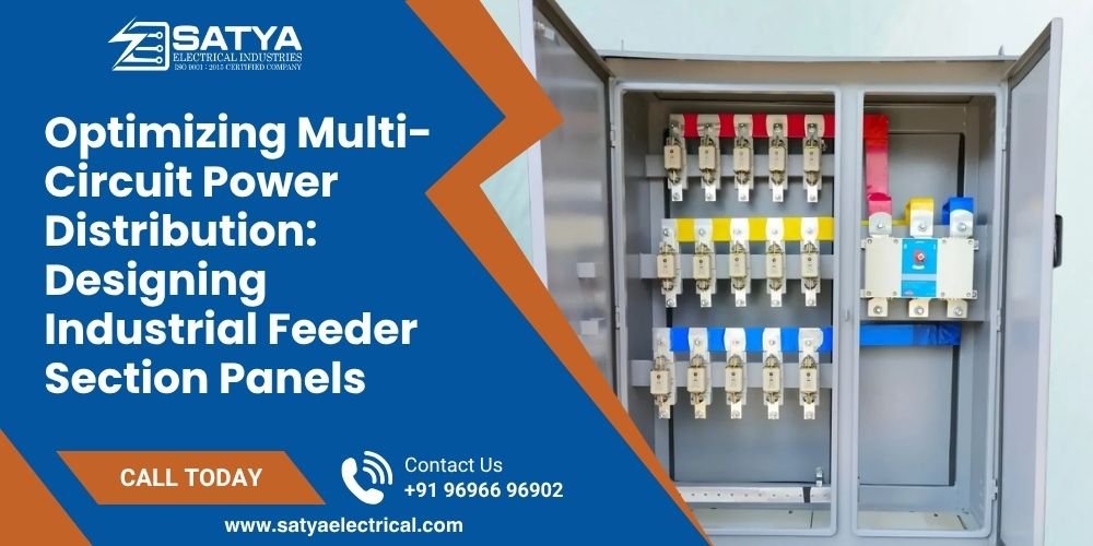
In large-scale industrial plants, managing power distribution is a balancing act of massive proportions. Raw electrical current arrives from the main utility transformer or substation breaker, but it cannot be fed directly into individual machinery lines. It must first be subdivided safely among a web of localized sub-systems, such as VFD Panels, heavy-duty heating networks, processing lines, and plant utilities.
The backbone of this critical middle-tier routing network is the Feeder Section Panel.
A feeder panel acts as the traffic cop for your electrical system. If it is designed with inaccurate busbar current densities, poor phase arrangements, or uncalculated safety factor spaces, a minor electrical fault on a single production machine can travel backward through the line. This triggers a cascading trip that shuts down the entire factory floor, causing massive operational losses.
The Architecture of Sub-Distribution: Ensuring Safe Circuit Isolation
The primary goal of a high-performance feeder panel is containment. If an electrical short circuit or motor overload occurs on “Line A,” the feeder panel’s protective switchgear must isolate that specific fault instantly, keeping “Lines B through Z” running without experiencing a momentary voltage dip.
To achieve this absolute separation, panel engineers utilize an infrastructure strategy known as Form-Factor Compartmentalization (under IEC 61439 standards):
- Individual Chambering: Every outgoing circuit feeder is housed inside its own sealed, independent sheet metal cubicle.
- Arc Flash Defense: By isolating each circuit’s protective switchgear—such as Molded Case Circuit Breakers (MCCB Panels) or specialized Switch Fuse Units—inside distinct metal pockets, an accidental arc flash occurring within one breaker compartment is fully contained. It cannot bleed sideways to damage adjacent breakers or ruin the central Bus Bar Chamber.
Critical Engineering Metrics for Feeder Section Panels
To build a reliable sub-distribution panel capable of running continuously under heavy factory environmental stress, engineers must balance rigid mechanical and electrical design limits:
| Engineering Design Parameter | Minimum Industrial Requirement | Operational Safety Purpose |
|---|---|---|
| Enclosure Rigidity (Sheet Steel) | 14 SWG (2.0mm) for load-bearing structures | Resists physical warping and securely supports heavy internal switchgear. |
| Short-Circuit Braking Capacity | 35 kA to 50 kA for 1 second | Ensures internal supports withstand magnetic forces during fault conditions. |
| Busbar Clearances (In Air) | Minimum 25 mm phase-to-phase and phase-to-earth | Prevents arc tracking and electrical breakdown in high humidity environments. |
| Internal Compartment Gasket | Flame-retardant Neoprene or EPDM profile | Seals compartments against dust, soot, and industrial contaminants. |
Phase Arrangement and the Danger of Current Unbalancing
[ Incoming Main Power: Red / Yellow / Blue Phases ]
                                     ||
               ======================||======================
               |       Central Copper Bus Bar Chamber       |
               ======================||======================
                     ||              ||              ||
                     \/              \/              \/
               [ Cubicle 1 ]    [ Cubicle 2 ]    [ Cubicle 3 ]
               - Line A Load    - Line B Load    - Line C Load
               (150 Amps)       (145 Amps)       (152 Amps)
                     ||              ||              ||
                     ----------------------------------
                                     ||
                    [ Target Balanced Neutral Current: ~0 Amps ]
One of the most destructive hidden challenges in multi-circuit systems is a highly unbalanced phase network. In a perfect industrial world, the electrical current drawn by the Red (R), Yellow (Y), and Blue (B) phases should be nearly equal.
If a plant layout team groups too many single-phase utility loads onto one phase, that specific phase line overheats, driving up conductor degradation. More dangerously, this imbalance forces heavy current to return back through the shared neutral line.
Because neutral bars inside standard panel enclosures are often downsized compared to the main phase bars, an unmitigated neutral current surge will trigger severe thermal degradation, destroying cable insulation and potentially sparking an electrical fire.
Engineering Calculation Rule: When layout designers structure a multi-circuit feeder section, they must include a minimum 25% active safety space factor margin on both the main copper busbar cross-section area and the physical enclosure space. This space buffer allows the factory to plug in future production machinery expansions without needing to replace the entire upstream sub-station switchgear array.
Deploy Vetted, Continuous-Duty Sub-Distribution Switchgear
Engineering high-capacity sub-distribution networks demands precision assembly methods and strict component vetting. Cutting corners on sheet metal gauges, partition dividers, or busbar air clearances risks catastrophic panel damage and systemic plant outages.
At Satya Electrical, we design and manufacture premium, heavy-duty Feeder Section Panels, Main Distribution Boards, and Custom Bus Bar Assemblies engineered strictly to match your precise kA fault ratings and operational load targets.

 Users Today : 4
 Users This Month : 104
 Total Users : 1317