
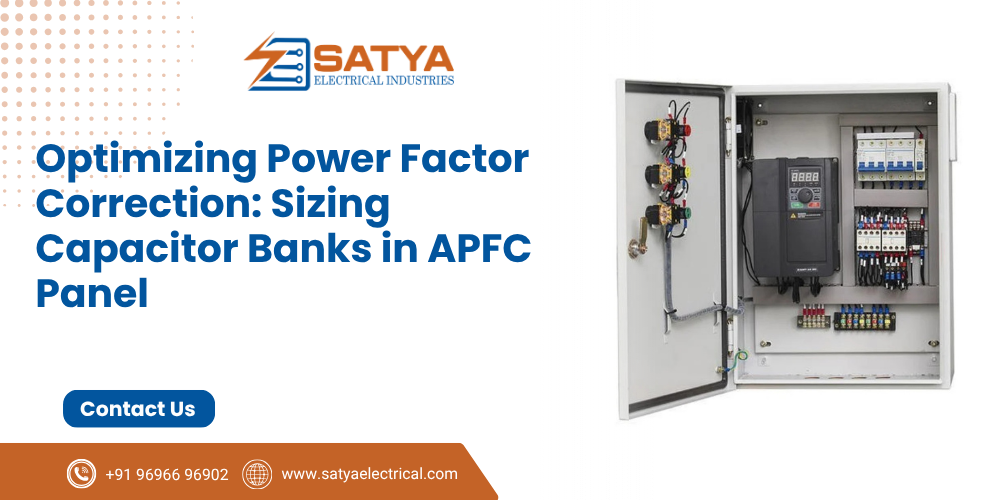
In heavy industrial facilities, motor-driven equipment—such as pumps, compressors, conveyers, and extrusion lines—operates primarily on inductive loads. These machines require two types of electrical energy to run: active power ( kW ) to perform real mechanical work, and reactive power ( kVAR ) to sustain the magnetic fields within their copper windings.
When a plant draws high reactive power directly from the utility grid, its Power Factor (cosΦ ) drops far below the ideal unity target (1.0).
This inefficiency forces utilities to impose heavy financial power factor penalties on your monthly energy bill. Installing an Automatic Power Factor Correction (APFC) Panel acts as a localized reactive power generator, supplying kVAR right at the plant busbar level.
However, improperly sizing the capacitor steps or ignoring background electrical harmonics will turn your APFC system into a ticking thermal time bomb.
The Mathematics of kVAR Sizing: Calculating the Delta
To size an APFC panel accurately, engineers must analyze the plant’s maximum active load demand ( kW ), the current average power factor ( cosΦ1), and the target power factor (cosΦ2).The required total reactive power compensation (QkVAR) is determined using the foundational trigonometric formula:
QkVAR = PkW × (tanΦ1 – tanΦ2)
Where: tanΦ = √((1 / cos²Φ) – 1)
Practical Example:
- Existing Plant Peak Active Load (P): 500 kW
- Initial Uncorrected Power Factor (cosΦ1): 0.75 Lagging (tanΦ1 approx 0.8819)
- Target Power Factor (cosΦ2): 0.99 Lagging tan Φ2 approx 0.1425)
QkVAR = 500 x ( 0.8819 – 0.1425 ) = 500 x 0.7394 = 369.7 kVAR
To bridge this gap safely, the plant requires a 370 x kVAR APFC Panel. Rather than installing one large 370 kVAR block, the system must be split into multiple smaller, intelligently stepped banks (e.g. 1 x 10 kVAR, 1 x 15 kVAR, 2 x 25 kVAR, 6 x 50 kVAR) managed by a micro-processor controller to match fluid load variations.
The Harmonic Threat: Why Detuned Reactors Are Essential
Modern factories rely heavily on variable frequency drives (VFD Panels), uninterrupted power supplies (UPS), and induction heaters. These non-linear loads produce high-frequency current harmonics (5th, 7th, 11th order waves).
                      [ Raw Power Grid Input ]
                                 ||
                =================================
                |  Main APFC Bus Bar Structure  |
                =================================
                   ||                       ||
                   \/                       \/
         [ Linear Capacitors ]    [ Non-Linear VFD Loads ]
                   ||                       ||
         (High-Freq Current)       (Harmonic Distortion)
                   ||                       ||
                   \========================/
                                ||
               !!! HARMONIC RESONANCE DANGER !!!
        (Current amplifies, causing capacitor rupture)
If standard power capacitors are connected directly across a busbar carrying heavy harmonic currents, the inductive reactance of the supply transformer matches the capacitive reactance of the panel at a specific frequency. This triggers Harmonic Resonance.
This resonance amplifies current levels by several hundred percent, leading to:
- Rapid thermal degradation and swelling of metal capacitor cans.
- Nuisance tripping of main feeder circuit breakers.
- Extensive harmonic distortion leaking back into the local power grid.
To eliminate this hazard, every high-performance APFC panel must integrate Detuned Series Reactors (typically rated at 7% or 14% tuning factors) in series with each capacitor bank. These reactors shift the resonant frequency of the system below the dominant harmonic orders, protecting the internal capacitors and scrubbing high-frequency noise from the busbar.
Critical Engineering Parameters for APFC Panels
To ensure continuous, fire-safe operational performance, APFC panels must meet rigid component and thermal build standards:
| Component / Parameter | Minimum Engineering Requirement | Operational Protection Goal |
| Capacitor Duty Specification | Heavy-Duty Polypropylene (MPP) Self-Healing | Survives unexpected transient voltage spikes without dielectric rupture. |
| Switching Duty Contactors | Specialized Duty Contactors with Pre-charging Resistors | Damps massive inrush currents during rapid bank switching cycles. |
| Enclosure Thermal Extraction | Forced-air cooling fan with dust filters | Keeps internal panel ambient temperature strictly below 45°C |
| APFC Controller Brain | Automatic step cycling with intelligent rotation | Distributes runtime hours evenly across all internal contactors. |
Inspection Rule: Capacitors lose their dielectric strength over time when exposed to continuous heat. Maintenance personnel should measure the actual operating current draw (Amps) of each capacitor step every quarter using a true-RMS clamp meter. A drop in phase current of more than $10\%$ indicates severe internal capacitance loss, signaling that the bank must be replaced before it causes power factor degradation.
Eliminate Utility Penalties with Precision Power Factor Solutions
Optimizing plant energy efficiency requires deep electrical harmonic analysis and precision switchgear assembly. Deploying under-rated capacitors or omitting detuned reactors leaves your main utility connections exposed to severe harmonic resonance, equipment failure, and heavy monthly power penalties.
At Satya Electrical, we design and manufacture high-efficiency APFC Panels, Detuned Reactor Banks, LT Power Factor Management Switchgear, and Custom Capacitor Enclosures tailored strictly to eliminate utility surcharges and protect your facility against power pollution.

 Users Today : 3
 Users This Month : 113
 Total Users : 1326